
Acrylic CNC Milling & Precision Drilling: DFM Reference
Design Challenge Overview
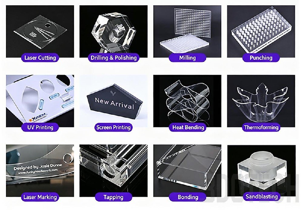
CNC machining is the foundation of precision acrylic fabrication, enabling complex features such as grooves, slots, holes and contoured surfaces with tight dimensional tolerances. However, acrylic's unique material properties — poor thermal conductivity, tendency to melt and re-adhere, and brittleness — make it prone to specific machining defects that are not encountered with metals or engineering plastics.
Common issues include melted chip adhesion (gumming), fogged groove walls, hole entry/exit chipping, and stress cracking — problems that often appear only after secondary operations or assembly, leading to costly scrap. This reference covers CNC slot milling and precision drilling processes, including tool selection, parameter optimization and design best practices to ensure consistent, production-ready results. Drawing on extensive fabrication experience, 3DOTECH engineering teams regularly encounter these challenges and have developed optimized parameter sets for each process.
DFM Optimization Guidelines
1. CNC Slot Milling Process
Acrylic slot milling is performed on CNC machining centers using single-flute carbide end mills with large chip gullets and mirror-finish cutting edges. Climb milling is preferred to reduce groove wall roughness. Standard parameters include 14,000 RPM spindle speed, 1200 mm/min feed rate, and maximum 3mm depth per cut, with continuous air cooling to remove cutting heat and prevent melted chip adhesion.
Key process details:
-
Groove precision: Up to ±0.1mm with crystal-clear, fog-free groove walls
-
Capable geometries: Straight slots, array card slots, irregular curved grooves and other complex structures
-
Deep slot strategy: Progressive layered cutting with atomized micro-coolant for temperature balance, preventing bulging and whitening deformation
-
Pre-production validation: Always test cut with same-batch scrap material to optimize parameters
-
Optical-grade upgrade: Ultra-fine tool edge polishing further improves groove wall light transmission uniformity for laboratory precision consumables
The single-setup multi-slot capability, combined with automated tool change systems, makes this process highly efficient for complex modular structures. Applications include bio-lab microplate base slots, automation equipment plastic guide rails, and retail display shelf retention features.
2. Precision Drilling Process
Acrylic drilling requires plastic-specific drill bits with 60°–90° point angles — not the standard 118° metalworking bits — to fundamentally reduce entry chipping and exit blowout defects. The standardized process involves pilot hole drilling followed by stepped reaming to final size, with low-speed, light-pressure feed and intermittent retraction for chip clearing, combined with water mist spray to control cutting heat buildup.
Critical parameters and techniques:
-
Spindle speed (thin sheets): 1000–2000 RPM, progressively reduced for thicker materials
-
Hole diameter precision: ±0.08mm for standard applications
-
Hole types: Array reagent wells, equipment mounting through-holes, hidden countersunk holes
-
Array drilling: CNC multi-axis positioning platforms achieve hole position consistency within 0.05mm
-
Large diameter holes: Multi-step reaming ensures smooth hole walls, with optional tapping for threaded assembly
Critical note: Acrylic has extremely poor thermal conductivity and high brittleness. Continuous high-speed drilling easily causes bit gumming and sheet cracking. Always use neutral cutting lubricant and never force-feed the drill. Common applications include bioassay microplates, electronic terminal panels, precision instrument housings and detachable display modules.
Key Specification Reference
DFM Best Practices & Support
-
Always specify plastic-specific tooling in manufacturing drawings — standard metalworking tools cause chipping, melting and poor surface finish on acrylic.
-
Design groove depths in multiples of 3mm or less to minimize layered cutting passes and reduce production time.
-
For hole arrays, specify minimum hole spacing to avoid material weakening and cracking between adjacent holes.
-
Include pilot hole and stepped reaming requirements in drawing notes for holes requiring high wall quality or tight tolerance.
3DOTECH provides precision CNC machining services for custom acrylic components, including slot milling, drilling, contouring and complex 3D machining. Our engineering team can review your design for CNC manufacturability, optimize feature dimensions for acrylic material properties and recommend the right tooling strategy. If you have an acrylic project requiring precision CNC machining, our team is ready to provide DFM assessment and prototyping support to ensure production-ready results from the first batch.
More from the Acrylic Fabrication Series
Once you've machined your acrylic parts, these additional processes can help you achieve the final product:
For precision cutting and detailed engraving, see Laser Cutting & Laser Engraving.
For premium edge finishes and surface textures, refer to Diamond Polishing & Sandblasting.
For strong, clean assembly methods, explore Tapping & Solvent Bonding.
For branding and decorative graphics, check out UV Printing & Screen Printing.
For 3D shapes and curved components, learn about Hot Bending & Vacuum Thermoforming.
For choosing the right base material, discover Cast vs. Extruded Acrylic Selection.
 Silicone Wall Thickness Design Principles
 Colors to Avoid in Custom Silicone Product Design
 Silicone Design Pitfall Guide Part 2: Uneven Wall Thickness
 5 Silicone Molding Processes
 Acrylic Tapping & Solvent Bonding: Assembly DFM Reference
 Acrylic CNC Milling & Precision Drilling: DFM Reference
 Acrylic Diamond Polishing & Sandblasting: Surface DFM
 Acrylic Laser Cutting & Engraving: DFM for OEM Designers
 Silicone Design Pitfall Guide Part 3: Missing Draft Angles